![]()  Introduction
Background
Features
History
Downloads
About us
Introduction
Background
Features
History
Downloads
About us
|
|
PiP: a software for calculating vibration from underground railways
Developed by: Dr. Mohammed Hussein and Dr. Hugh Hunt
PiP stands for "Pipe in Pipe". It describes the essential nature of the model in its original formulation where two concentric pipes are used to model a tunnel embedded in a full space. The inner pipe accounts for the tunnel wall and the outer pipe has an external outer surface with infinite radius to account for a full space with a cylindrical cavity.
The model used in the current version of the software (version 4) performs calculations of vibration due to a train of infinite length moving on a slab track coupled to a circular tunnel embedded in a half space.
The following steps are followed to calculate the PSD of the vertical vibration in soil due to a train moving on a rail with a given roughness spectrum:
1. Calculating forces at the wheel-rail interface
A train of infinite length is represented by infinite number of axle masses with a constant spacing moving on a track as shown in Figure 1. Due to low stiffness of primary suspensions of modern trains,
it is reasonable to ignore sprung masses in such a model. As shown in Figure 1, a model of double-beams supported on elastic foundation is used to calculate forces at the wheel-rail interface. This has been found to improve the efficiency of calculations without reducing the accuracy of results.
The source of excitation in this model is the track irregularity which is represented by relative displacements between the axles and the rail. The relative displacements are defined as uncorrelated random inputs.
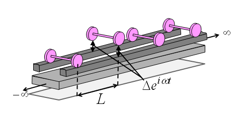 Figure 1. A roughness excitation is applied as an input to the model (railpads and slab bearings are not shown)
2. Calculating transfer functions of the track-tunnel-soil system
To calculate displacements in the soil due to forces applied at the rails as resulted from the previous step, a model of double-beam coupled to a tunnel embedded in a half-space is used. The model is shown in Figure 2 and it is used to calculate transfer functions between the rails and soil. The track is coupled to the tunnel-soil system in the wavenumber-frequency domain by using frequency-response-functions of the double-beam system and the tunnel-soil system. To calculate transfer functions for the tunnel-soil system, i.e. for a tunnel embedded in a half-space, an assumption is made which results in efficient, yet accurate computations. The assumption states that displacements at the tunnel-soil interface due to a source inside the tunnel are the same whether there is a free-surface or not. The accuracy of this assumption increases with the increasing depth of tunnel. To calculate vibration in the soil due to any input at a tunnel embedded in a half-space, the following steps are used
2.1. the displacements at the tunnel-soil interface are calculated using the original version of the PiP model, i.e. using a model of a tunnel embedded in a full space;
2.2. the internal source in a full space that produces the displacements at step 2.1 is calculated using a variant to the PiP model which accounts for a full space. This time, a two concentric pipes are used, the internal accounts for a solid cylinder and the external accounts for a full space with a cylindrical cavity. Both pipes are modelled using the elastic continuum theory;
2.3. the internal source calculated in step 2.2 along with Green's functions for an elastic half-space (as derived by Tadeu et al.) are used to calculate vibration at the far field.
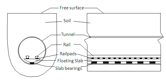
Figure 2. The track-tunnel-soil system used by the software
Vibration outputs are calculated at points in the soil in the same cross-section of one of the axle masses, see Figure 1. These calculations are based on the assumption that vibration does not vary along a line parallel to the tunnel. This assumption is good at distances away from the tunnel that are large compared with the axle spacing.
References
[1]
M.F.M. Hussein, and H.E.M. Hunt, A software application for calculating vibration
due to moving trains in underground railway tunnels. In: NOVEM2009: Noise and Vibration: Emerging Methods,
Oxford, UK, 5th-8th of April, 2009. [pdf]
[2]
M.F.M. Hussein, S. Gupta, H.E.M. Hunt, G. Degrande, J.P. Talbot,
An efficient model for calculating vibration from a railway tunnel embedded in a half-space,
the International Congress of Sound and Vibration, Vienna, Austria, 2006.[pdf]
[3] M.F.M.Hussein and H.E.M.Hunt. An Insertion Loss Model for
evaluating the performance of floating-slab track for underground
railway tunnels, ICSV10, Sweden, 2003. [pdf]
[4] J.A. Forrest and H.E.M. Hunt, Ground vibration generated by
trains in underground tunnels, Journal of Sound and Vibration.[http]
[5] J.A. Forrest and H.E.M. Hunt, A three-dimensional tunnel
model for calculation of train-induced ground vibration, Journal of
Sound and Vibration.[http]
[6]
A. Tadeu, J. Antonio, and L. Godinho, Green’s function for two-and-a-half dimensional
elastodynamic problems in a half-space., Computational Mechanics, 27, 6, 484-491 (2001).
[7]
F. Frederich, Die Gleislage - aus fahrzeugtechnischer Sicht
[Effect of track geometry on vehicle performance]. Zeitschrift fur
Eisenbahnwesen und Vekehrstechnik - Glaser Annalen, 108, 12, 355-362, 1984.
|